

Commercial Helical Piles Installation
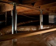
For new construction and retrofit deep foundation projects, Foundation Recovery Systems uses helical piles in both tension and compression load applications.
Get Your Free EstimateFor new construction and retrofit deep foundation projects, Foundation Recovery Systems uses helical piles in both tension and compression load applications.
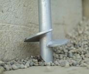
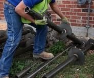
Helical piles are a factory-manufactured steel foundation system consisting of a central shaft with one or more helix-shaped bearing plates, commonly referred to as blades or flights, welded to the lead section. Extension shafts, with or without additional helix blades, are used to extend the pile to a load-bearing strata and to attain design depth and capacity. Brackets are used at the tops of the piles for attachment to structures, either for new construction or retrofit applications. Torque is applied to the helical piles to secure them into the ground.
Specifiers often interchangeably use the terms helical piles, screw piles, helical piers, helical anchors, helix piers, and helix anchors. However, the term ‘pier’ more often refers to a helical pile loaded in axial compression, while the term ‘anchor’ more often refers to a helical pile loaded in axial tension.
Advantages of Helical Foundation Systems
- High-capacity deep foundation alternative.
- All-weather installation – Helical piles can be installed through inclement weather and freezing temperatures.
- Installed in areas of limited or tight access – The equipment and drive heads can be sized according to the project design loads, as well as site access.
- Vibration-free installation – Unlike traditional driven piles or rammed aggregate soil improvement options, rotary installation of helical piles does not produce ground vibrations.
- Install quickly without generating spoils – Helical piles do not auger soils to the surface. Therefore, there are no hauling or disposal costs.
Design Considerations
Helical piles are designed such that most of the axial capacity of the pile is generated through bearing of the helix blades against the soil. To prevent one blade from contributing significant stress to the bearing soil of the adjacent blade, the helix blades are typically spaced three diameters apart along the pile shaft. Significant stress influence is limited to a ‘bulb’ of soil within about two helix diameters from the bearing surface in the axial direction and one helix diameter from the center of the pile shaft in the lateral direction. Each helix blade therefore acts independently in bearing along the pile shaft.
Multiple piles shall have a center to center spacing at the helix depth of at least four (4) times the diameter of the largest helix blade (ICC-ES AC358). The tops of the piles may be closer at the ground surface but installed at a batter away from each other in order to meet the spacing criteria at the helix depth. The uppermost helix blade shall be installed to a depth of at least twelve (12) diameters below the ground surface (ICC-ES AC358) for tension applications.
DETERMINATION OF CAPACITY
The ultimate capacity of a helical pile may be calculated using the traditional bearing capacity equation:
Qu = ∑ [Ah (cNc + qNq)]
|
Where: |
|
Qu |
= |
Ultimate Pile Capacity (lb) |
Ah |
= |
Area of Individual Helix Plate (ft2) |
c |
= |
Effective Soil Cohesion (lb/ft2) |
Nc |
= |
Dimensionless Bearing Capacity Factor = 9 |
q |
= |
Effective Vertical Overburden Pressure (lb/ft2) |
Nq |
= |
Dimensionless Bearing Capacity Factor | ||||||||||||||||||
|
Qu |
= |
Ultimate Pile Capacity (lb) | |||||||||||||||||||||||||||||||||||
|
Ah |
= |
Area of Individual Helix Plate (ft2) | |||||||||||||||||||||||||||||||||||
|
c |
= |
Effective Soil Cohesion (lb/ft2) | |||||||||||||||||||||||||||||||||||
|
Nc |
= |
Dimensionless Bearing Capacity Factor = 9 | |||||||||||||||||||||||||||||||||||
|
q |
= |
Effective Vertical Overburden Pressure (lb/ft2) | |||||||||||||||||||||||||||||||||||
|
Nq |
= |
Dimensionless Bearing Capacity Factor |
Total stress parameters should be used for short-term and transient load applications and effective stress parameters should be used for long-term, permanent load applications. A factor of safety of 2 is typically used to determine the allowable soil bearing capacity, especially if torque is monitored during the helical pile installation.
There are many factors to be considered in designing a helical pile foundation, like other deep foundation alternatives. We recommend that helical pile design be completed by an experienced geotechnical engineer or other qualified professional.
Correlation to installation torque is another well-documented and accepted method for estimating helical pile capacity. In simple terms, the torsional resistance generated during helical pile installation is a measure of soil shear strength and can be related to the bearing capacity of the pile.
Qu = KT
|
Where: |
|
Qu |
= |
Ultimate Pile Capacity (lb) |
K |
= |
Capacity to Torque Ratio (ft-1) |
T |
= |
Installation Torque (ft-lb) | |||||||||
|
Qu |
= |
Ultimate Pile Capacity (lb) | |||||||||||||||||
|
K |
= |
Capacity to Torque Ratio (ft-1) | |||||||||||||||||
|
T |
= |
Installation Torque (ft-lb) |
The capacity to torque ratio is not a constant and varies with soil conditions and the size of the pile shaft. The best way to determine project specific K-values is load testing using the proposed helical pile and helix blade configuration. However, ICC-ES AC358 provides default K-values for varying pile shaft diameters, which may be used conservatively for most soil conditions. The default value for the Model 288 Helical Pile System (2 7/8-inch diameter) is K = 9 ft-1.
Contact us to discuss your Helical Foundation Project
We service Greater Kansas City and Missouri, including St. Louis, Columbia, Moberly, Springfield, Decatur, and all of Central Missouri and Eastern Kansas. Contact us today for a free foundation repair inspection!
Explore more solutions


Our Locations
3349 Southgate Ct SW,
Cedar Rapids, IA 52404
(319) 220-5034
14678 E 925 North Rd, Building 5
Bloomington, IL 61705
2401 SE Creekview Dr.
Ankeny, IA 50021
(515) 373-8491
7280 NW 87th Terrace, Suite C-210
Kansas City, MO 64153
(816) 774-1539
211 SE State Route 150
Lee's Summit, MO 64082
(816) 774-1539
1872 State Hwy M
Moberly, MO 65270
(660) 202-8662
3020 N. Martin Ave.
Springfield, MO 65803
(417) 612-8286
1625 Larkin Williams rd.
Fenton, MO 63026
(314) 207-9995